Quick answer
Use a 6 inch attenuation filter when a highly reflective test part produces fringes that are too bright or washed out, and place it between the test part and the transmission flat at the specified angle of incidence to restore contrast without changing the test setup.
Why attenuation helps with high reflectivity samples
Highly reflective parts can return so much light that the interferometer camera saturates, making fringe contrast poor and measurement unreliable. An attenuation filter reduces the beam intensity before it reaches the camera, so you keep the same optical path and alignment while bringing the signal into a usable range.
The 6 inch Attenuations Filter is designed for this job: it transmits about 20% at 632.8 nm when tilted to a 10° angle of incidence, and its transmitted wavefront is specified as ≤ λ/10 PVr. That means it dims the beam without adding significant wavefront error of its own, which matters when you are measuring tight surface figures.
When to choose a 6 inch filter over a 4 inch
The main reason to step up to a 6 inch filter is aperture. If your test beam or transmission flat is larger than 4 inches, a smaller filter will vignette the beam and you will lose valid data at the edges. The 6 inch size covers a wider beam so the entire clear aperture is attenuated uniformly.
If your setup uses a 4 inch transmission flat and the beam never exceeds that, a 4 inch filter is usually sufficient and may be easier to mount in tight spaces. The 6 inch filter is the better choice when you need the extra clear aperture or when you want one filter to cover multiple setups with larger beams.
Mounting and angle considerations
The filter is specified for use at a 10° angle of incidence. Tilting the filter avoids etalon effects and keeps the transmitted beam separate from any front-surface reflection. A kinematic mount with fine angular adjustment makes it practical to hit that angle repeatably.
Because the filter is placed between the test part and the transmission flat, check that your mount does not intrude into the clear aperture and that the filter surface is clean before each measurement. Even a small dust particle in the beam path can scatter light and mimic a defect.
Step-by-step setup for the 6 inch attenuation filter
- Confirm the need for attenuation: Start with your standard setup and observe the fringe pattern. If fringes are saturated or contrast is poor, and the test part is highly reflective, proceed with the filter. Do not add the filter if fringes are already well contrasted and the camera is not clipping. Check the camera histogram or fringe visibility before adding the filter; unnecessary attenuation can reduce signal-to-noise.
- Position the filter in the beam path: Place the filter between the test part and the transmission flat, centered on the beam. Ensure the mount does not block the clear aperture. Use a mount that allows fine tilt adjustment. Keep the filter perpendicular to the beam only during initial placement; you will tilt it in the next step.
- Set the angle of incidence to 10°: Tilt the filter to approximately 10° from normal incidence. Use a rotation stage or a kinematic mount with a scale if available. Verify the angle with a reference or by checking that the transmitted beam is offset as expected. A common mistake is leaving the filter at normal incidence, which can cause unwanted etalon fringes and changes the specified transmittance.
- Recheck fringe contrast and exposure: After inserting and tilting the filter, adjust the camera exposure or gain if needed. The goal is to fill the camera's dynamic range without clipping. Compare the fringe contrast to the unfiltered case; it should improve for a highly reflective sample. If contrast does not improve, verify that the filter is actually in the beam and that the angle is correct.
- Clean and inspect before each measurement: Use proper optics cleaning procedures to remove dust from the filter surfaces. Inspect the filter under a light before installing it in the beam path. A dirty filter can scatter light and create false defects; make cleaning a routine checkpoint.
Product facts
-
6 inch Attenuations Filter: Transmittance is 20 ± 4% at 10° angle of incidence at λ=632.8 nm. This predictable reduction lets you estimate whether the filter will bring your signal into the camera's linear range without trial and error.
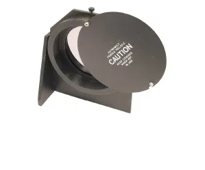
6 inch Attenuations Filter
-
6 inch Attenuations Filter: Transmitted wavefront is specified as ≤ λ/10 PVr. A low transmitted wavefront error means the filter itself will not significantly distort the measurement of your test part.