Quick answer
Treat the G1000NXI 3-piece set as three separate displays and one audio unit: mount each panel where your eyes and hands naturally fall, connect each screen by its own HDMI and USB link, then configure MSFS to match the physical layout before you fly.
Plan the cockpit layout before you drill
The PFD and MFD are both 10.4-inch wide-view displays, so the pair consumes significant panel width. Sit in your normal flying position and mark where each screen center lands relative to your eye line; a PFD placed too far right forces constant head turns during approach.
The GMA audio panel belongs within easy reach of your throttle hand, not between the screens. Keep the three units close enough that their USB and HDMI cables can reach a powered hub without strain.
Cable routing is the hidden constraint
Each display needs HDMI for video and USB for power and data. Plan a route that keeps video cables away from power supplies and audio wiring; if you must cross them, do so at right angles. Leave a service loop behind each panel so you can pull a unit forward for cleaning or troubleshooting without disconnecting everything.
When the plug-and-play claim still needs a check
The set ships with drivers preloaded for plug-and-play operation, but Windows may still assign the two displays in an unexpected order. Verify display numbering in the OS before launching the simulator, because MSFS will inherit that order when you assign PFD and MFD roles.
Step-by-step G1000NXI panel setup
- Mount the PFD first: Use the supplied brackets to fix the PFD at your primary eye line, slightly left of center. Tighten the brackets only after you confirm the screen is level and the HDMI and USB ports remain accessible. Common mistake: mounting flush against a side wall and blocking cable access. Check cable clearance before final tightening.
- Mount the MFD beside it: Place the MFD to the right of the PFD with a consistent gap, using the same bracket method. Sit in your flying position and confirm both screens are readable without leaning. Common mistake: spacing the MFD too far right, which makes cross-checking during approaches uncomfortable. Both screens should fall within a single glance.
- Position the GMA audio panel: Mount the audio panel within reach of your throttle hand, typically below or outboard of the MFD. Route its USB cable separately from the display HDMI runs. Common mistake: burying the audio panel behind the screens where you cannot reach the buttons in flight. Reach the audio panel without releasing the throttle.
- Connect USB and HDMI in a fixed order: Connect each display's HDMI to a dedicated PC output and its USB to a powered hub, then connect the audio panel. Power on the PC last. Common mistake: daisy-chaining unpowered hubs, which can cause one screen to drop out intermittently. Use a powered hub for all three USB connections.
- Verify display order in Windows: Open Windows display settings and identify which physical screen is Display 1 and Display 2. Rearrange the virtual layout to match your physical left-to-right order. Common mistake: skipping this and later assigning the PFD role to the MFD in the simulator. Label each cable end once you confirm the order.
- Configure MSFS G1000NXI roles: In MSFS, assign the PFD to the left display and the MFD to the right, then test the audio panel by toggling a COM frequency. Common mistake: assuming the simulator auto-detects the correct panel; always verify with a short flight. Run a five-minute pattern before a longer session.
Product facts that affect setup
-
1/1 Scale G1000NXI Integrated Avionics 3-Piece Panel Set (PFD+MFD+Audio) with Mounting Brackets - Compatible with Major Flight Simulators: Includes G1000 PFD, MFD and GMA audio panel, with both screens using 10.4-inch wide-view HDMI displays and backlit buttons. Two full-size screens and a separate audio unit mean you need a panel plan that accommodates three distinct mounting positions, not a single cutout.
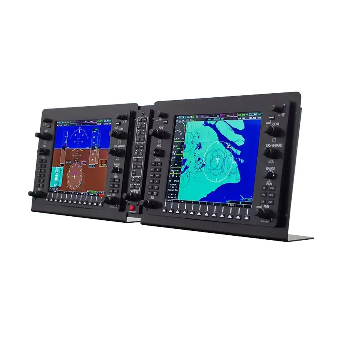
1/1 Scale G1000NXI Integrated Avionics 3-Piece Panel Set (PFD+MFD+Audio) with Mounting Brackets - Compatible with Major Flight Simulators
-
1/1 Scale G1000NXI Integrated Avionics 3-Piece Panel Set (PFD+MFD+Audio) with Mounting Brackets - Compatible with Major Flight Simulators: Connects to your PC via USB and HDMI and comes preloaded with drivers for plug-and-play operation. You can skip manual driver hunting, but you still need enough USB ports and HDMI outputs on your PC or hub for three devices.
-
1/1 Scale G1000NXI Integrated Avionics 3-Piece Panel Set (PFD+MFD+Audio) with Mounting Brackets - Compatible with Major Flight Simulators: Compatible with major flight simulators and supplied with mounting brackets. The brackets let you fix each panel securely, which matters more than usual because the PFD and MFD are separate units that can shift independently if only loosely mounted.