Start with the sensor's fixed limits
The Infrared Obstacle Avoidance Sensor IR Photoelectric from Kunkune is a reflective IR module with a digital output, not a distance sensor. It emits IR light and detects the reflection from an object within 2–40cm, then drives its output LOW when something is detected and HIGH when the path is clear. That active-low behavior matters when you write your sketch: a LOW reading means an obstacle, not a fault.
The module runs from 3.3V to 5V and can connect directly to Arduino, ESP32, and Raspberry Pi GPIO without a level shifter. The LM393 comparator cleans up the phototransistor signal and provides over 15mA drive capacity, which is enough for a clean TTL signal into a microcontroller input. An onboard potentiometer sets the detection distance, and an indicator LED gives visual feedback when the output changes.
Wiring the IR photoelectric sensor to your board
Use this sequence for a first test on Arduino, ESP32, or Raspberry Pi. The module's supply range covers all three, so the main differences are pin naming and logic voltage.
- 1. Identify the three pins: The module has VCC, GND, and OUT. Connect VCC to the board's 3.3V or 5V supply, GND to ground, and OUT to a digital GPIO input. The catalog confirms direct GPIO connection across the supported boards, so no level shifter is needed.
- 2. Power the module within 3.3V–5V: Do not exceed the stated supply range. On a 5V Arduino, the 5V pin is fine. On ESP32 or Raspberry Pi, use the 3.3V rail unless your board's documentation confirms the GPIO is 5V tolerant.
- 3. Read the output as active low: When the sensor detects a reflection, OUT goes LOW. When clear, OUT stays HIGH. In code, treat LOW as 'obstacle present' and HIGH as 'clear'.
- 4. Watch the onboard LED during the first test: The indicator LED gives immediate visual feedback. If the LED never changes state as you move an object in front of the sensor, check supply and ground before changing code.
What the catalog confirms for this module
-
Infrared Obstacle Avoidance Sensor IR Photoelectric: 2cm–40cm detection range, potentiometer adjustable This is the working range you can expect before adjustment; the potentiometer lets you narrow or widen detection within those limits.
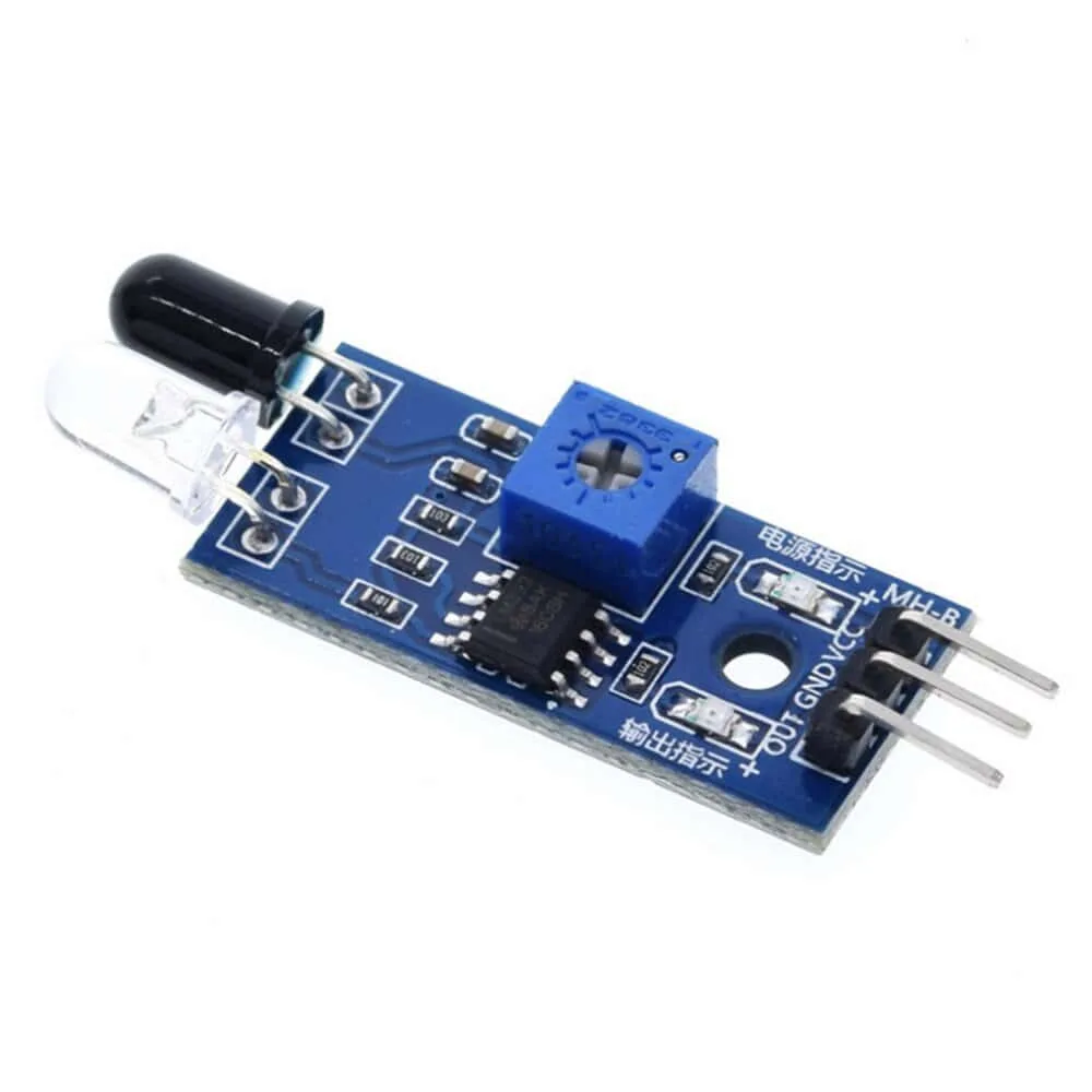
Infrared Obstacle Avoidance Sensor IR Photoelectric
-
Infrared Obstacle Avoidance Sensor IR Photoelectric: 3.3V–5V supply — direct GPIO connection to Arduino, ESP32, and Raspberry Pi You can test on any of these boards without adding a level shifter, provided you stay within the supply range.
-
Infrared Obstacle Avoidance Sensor IR Photoelectric: LM393 comparator — clean TTL signal, active low The comparator output is a digital LOW on detection and HIGH when clear, so your code reads a simple binary state rather than an analog voltage.
Adjusting the potentiometer for reliable range
The onboard potentiometer is the only range control on this module. Turn it while watching the indicator LED and moving a target object at the distance you care about. The goal is to find the point where the LED changes state consistently at that distance, not to max out the range.
Because the sensor relies on reflected IR, the object's surface and angle affect detection more than the potentiometer does. A flat, light-colored target at a fixed distance is the easiest to detect. Dark, angled, or soft surfaces reflect less IR and may need a closer target or a different potentiometer position. The catalog does not specify a recommended distance for any particular material, so treat the 2–40cm figure as the module's working envelope and tune within it for your actual target.
For an Arduino line follower sensor setup, the same potentiometer sets how far the sensor 'sees' the line. Start with the sensor close to the surface and adjust until the LED responds to the line but not to the background. If the line and background both trigger the sensor, the range is set too wide for that contrast.
Range adjustment checkpoints
Use these checks before you assume the module is faulty or the code is wrong.
- LED responds but code does not: Confirm the OUT pin is connected to the same GPIO number used in your sketch, and that the sketch treats LOW as detection.
- Detection is erratic at the edge of range: Turn the potentiometer to reduce the detection distance until the output is stable for your target. Edge-of-range readings are the least reliable.
- No detection at any potentiometer position: Check supply voltage and ground first, then confirm the target is within 2–40cm and has a reflective surface facing the sensor.
- Detection triggers with nothing in front: Reduce the potentiometer setting. Nearby surfaces or strong reflections can fall inside a wide detection range.
Where this sensor fits and where it does not
The catalog lists robot obstacle avoidance, conveyor belt item detection, automatic hand sanitiser triggers, bin lid sensors, edge detection for line followers, and touchless switches as suitable applications. These all rely on a simple detected/clear decision rather than a measured distance.
If your project needs the actual distance to an object, this module is not the right part: its output is digital, not analog or proportional. The catalog does not confirm any distance-measurement output, so plan a different sensor for that job. For a binary 'something is here' check within 2–40cm, the LM393 comparator and adjustable potentiometer make this a straightforward choice.
The module is available as a single Standard variant. For orders of 10 or more units, Kunkune offers trade pricing on request. The catalog lists 60-day returns with no minimum order, and stock ships from the UK via Royal Mail.