What the LOC-I Striker X Kit Includes
The LOC-I Striker X is designed as a first rocket kit, especially for classroom or group settings. The airframe comes pre-slotted, and the material is described as twice the thickness of typical model rocket tubes, giving it extra durability for repeated flights. The kit includes a Kevlar shock cord and laser-cut birch plywood fins, both chosen for strength. You also get vinyl decals for finishing the rocket. An engine hook is included that accepts 18mm motors from A through D impulse.
Product Evidence for Your Build
-
LOC-I Striker X: The Striker X has a pre-slotted airframe that's 2x the thickness of others. A thicker tube means less risk of crushing during handling or when inserting the motor. It also makes the rocket more forgiving for first-time builders.
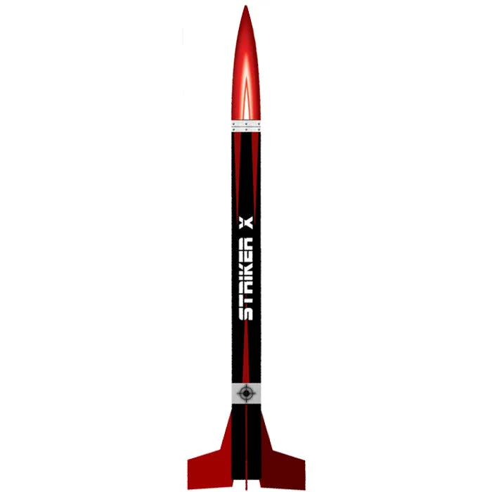
LOC-I Striker X
-
LOC-I Striker X: Kevlar shock cord and laser cut birch fins add to the durability and strength. Kevlar is heat-resistant and won't melt from ejection charges, so your recovery system stays reliable. Birch plywood fins resist splitting better than balsa.
-
LOC-I Striker X: An engine hook is included for 18mm motors ranging from A-D impulse. This tells you the motor mount is built for standard 18mm motors. You can choose from low-impulse A motors for small fields up to D motors for higher flights.
Assembly Sequence for the Striker X
The Striker X is designed for straightforward assembly. The following steps reflect typical build order for a pre-slotted kit like this one. Always refer to the included StrikerX Instructions for exact details.
- Prepare the motor mount: Install the engine hook into the motor tube. The hook holds 18mm motors from A to D. Center the motor tube inside the airframe using centering rings if provided (check your kit). Apply wood glue or epoxy to the rings.
- Attach the fins: The airframe is pre-slotted, so you can slide the laser-cut birch fins into the slots. Apply glue along the root edge and into the slot. Use a fin alignment jig or a simple square to keep them straight. Let the glue cure fully.
- Install the recovery system: Tie the Kevlar shock cord to the eyelet on the nose cone and to the motor mount or a loop inside the airframe. Attach the parachute or streamer (supplied separately) to the other end of the shock cord. Ensure the cord is long enough to prevent the nose cone from striking the airframe during deployment.
- Finish the rocket: Sand the fins and body tube lightly. Apply primer and paint as desired. Once paint is dry, apply the vinyl decals included in the kit. Decals go on best when the surface is clean and smooth.
First Launch Preparation
Before heading to the launch field, check that the recovery system is packed loosely so it deploys freely. Install an 18mm motor (A through D) into the motor tube; the engine hook will hold it in place. Use a launch pad that accommodates the rocket's length and weight. Insert an igniter into the motor nozzle and connect it to your launch controller. Verify the wind is calm and the field is large enough for the expected altitude. Always follow the NAR or TRA safety code for high-power model rocketry.
What the Catalog Does Not Cover
The supplied information does not specify the exact length or diameter of the Striker X airframe, nor the recommended launch rod size. For precise measurements, refer to the Striker X Rocksim File or measure the parts directly. The kit also does not include a parachute or streamer, so you will need to purchase one separately. The instructions are not reproduced in full here, so follow the printed manual for torque values, glue types, and cure times.