What This Guide Covers
This article explains how to set up and align the Zygo Motorized XY Stage, 12" x 14". It is a spare part designed for large gantry NexView systems. Because it is a non-encoded stage, alignment relies on external feedback rather than internal position reporting. This guide covers what the catalog confirms and what you need to verify before installation.
Stage Specifications from the Catalog
-
Motorized XY Stage, 12" x 14": Size: 12" x 14" Confirms the stage's physical footprint. Ensure your gantry system has a compatible mounting area.
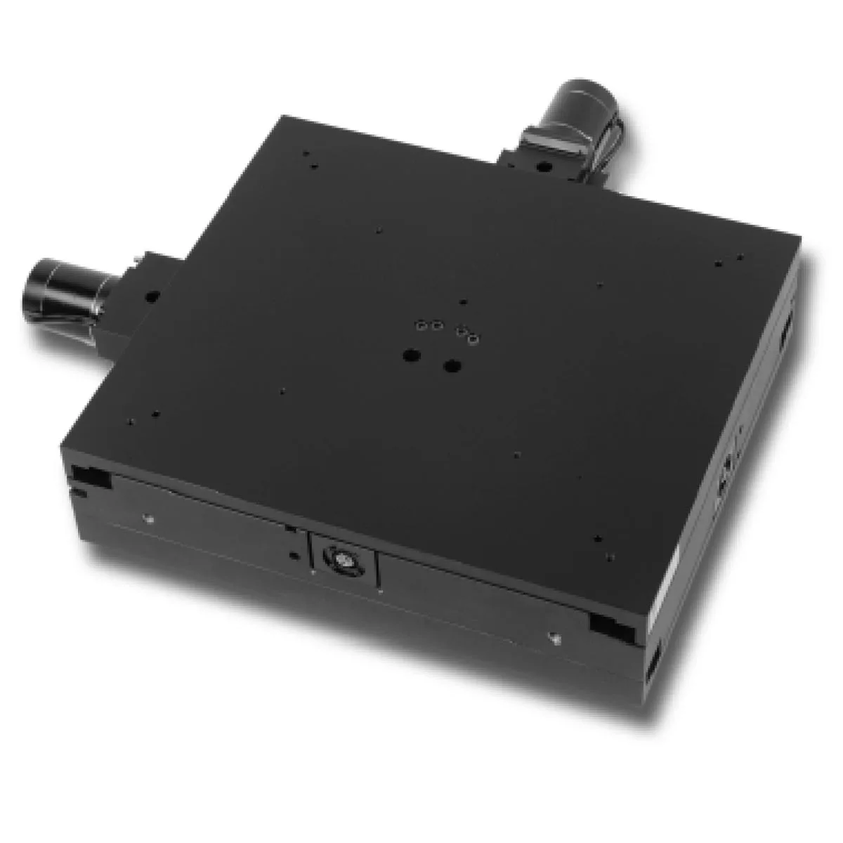
Motorized XY Stage, 12" x 14"
-
Motorized XY Stage, 12" x 14": Compatible with large gantry NexView systems Narrows down the intended use. This stage is not a generic replacement; it is specifically for NexView gantry platforms.
-
Motorized XY Stage, 12" x 14": Non-encoded stage design Without encoders, the stage does not report its position. You will need an external measurement system (e.g., laser interferometer or external encoder) for closed-loop positioning.
Pre-Installation Compatibility Check
Before you begin, verify that your NexView gantry system is a large gantry model. The catalog does not list a specific part number for the gantry, so check your system documentation or contact Zygo support if unsure. Also confirm that the 12" x 14" mounting footprint matches your existing stage mount. The stage is motorized, so ensure your controller supports the motor type and power requirements. The catalog does not specify voltage or connector type, so consult your controller manual.
Mechanical Installation Steps
The following steps are based on general best practices for replacing a similar motorized stage. The catalog does not provide detailed installation instructions, so these are recommended checkpoints.
- 1. Power Down and Isolate: Turn off and disconnect the gantry system from power to prevent accidental movement or electrical hazard.
- 2. Remove Existing Stage (if applicable): If replacing an old stage, carefully disconnect any cables and remove mounting screws. Support the stage to avoid dropping.
- 3. Mount the New Stage: Position the 12" x 14" stage onto the gantry mount. Use the same screw pattern if available. Tighten evenly but do not overtighten.
- 4. Connect Motor Cables: Connect the motor cables to your controller. Verify connector type and polarity. The catalog does not specify cable length or type, so use the cables that came with your system.
- 5. Initial Power-On Test: Power on the controller and test basic movement. Listen for unusual sounds. If the stage does not move, check cable connections and controller settings.
Alignment Considerations for a Non-Encoded Stage
Because the stage is non-encoded, you cannot rely on internal position feedback. Alignment must be done using an external reference. For optical systems, this often means using a laser interferometer or a camera-based alignment tool. The catalog does not provide alignment procedures, so consult your NexView system manual. A common approach is to move the stage to a known mechanical stop or use a dial indicator to verify position repeatability.
What the Catalog Does Not Cover
The catalog confirms the stage size, compatibility, and non-encoded design. It does not include wiring diagrams, motor specifications, software setup, or alignment targets. For these details, refer to your NexView system documentation or contact Zygo support. The stage is a spare part, so it assumes the user has the necessary system knowledge.