Start with your motor tube, not the retainer
PRO Motor Retainers are sized by the inside diameter (ID) of the retainer and the outside diameter of your motor tube. The catalog lists distinct variants for LOC cardboard tubes and PML phenolic tubes, plus flanged versions for larger builds. Before you order, measure your motor tube’s outside diameter or confirm its material and nominal size. A retainer that is too loose will not bond reliably; one that is too tight will not seat.
The supplied specifications give exact IDs for each variant. Use those numbers as your primary fit check. If your tube is not LOC cardboard or PML phenolic, the catalog does not confirm a matching retainer, so you will need to verify fit independently.
Retainer IDs and the tubes they are sized for
-
PRO Motor Retainers: LOC PRO 29mm: 30.1 mm ID, sized for LOC cardboard motor tubes. Lets you confirm a 29mm LOC cardboard tube will fit before ordering.
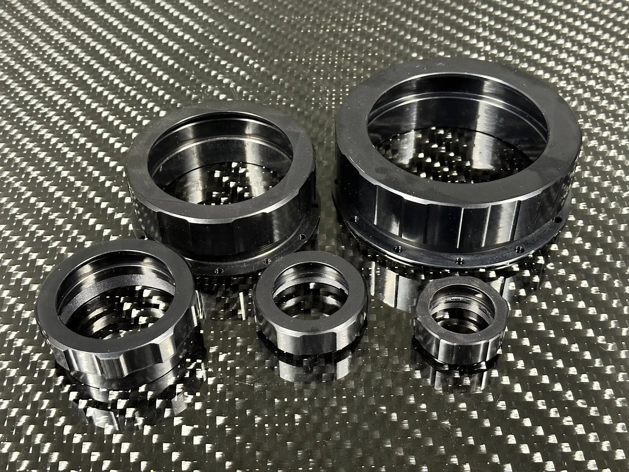
PRO Motor Retainers
-
PRO Motor Retainers: PML PRO 29mm: 32.4 mm ID, sized for PML phenolic motor tubes. Shows that PML phenolic tubes use a larger ID than LOC cardboard at the same nominal size.
-
PRO Motor Retainers: PML PRO 38mm: 42 mm ID, sized for PML phenolic motor tubes. Useful when upgrading a 38mm phenolic build.
-
PRO Motor Retainers: PML PRO 54mm: 58.1 mm ID, sized for PML phenolic motor tubes. Confirms the 54mm phenolic fit.
-
PRO Motor Retainers: PRO Flanged 75mm: flanged sleeve has a 75.5 mm ID, 98.4 mm flange OD, with 12 M3 holes in an industry standard pattern for mounting. Gives the mounting pattern and flange size for 75mm flanged installations.
-
PRO Motor Retainers: PRO Flanged 98mm: flanged sleeve has a 98.8 mm ID, 126.2 mm flange OD, with 12 M4 holes in an industry standard pattern for mounting. Gives the mounting pattern and flange size for 98mm flanged installations.
Two installation paths: epoxy or flange mount
The catalog describes two supported methods. For the LOC and PML variants, install the retainer onto the aft of your motor tube with BSI 15 minute epoxy. For the flanged 75mm and 98mm variants, install onto your flush aft ring using the included self-tapping socket head cap screws. The flanged method relies on the supplied screw pattern, not epoxy, so check that your aft ring can accept the screws.
The cap threads on with large square threads and plenty of travel, which the catalog notes allows quick motor changes in the field. That threading is part of the retainer’s design; no additional lubrication or thread treatment is specified in the supplied information.
Epoxy installation for LOC and PML retainers
- Dry-fit the retainer on the motor tube: Slide the retainer over the aft end of the tube. It should seat without forcing. If it rocks or binds, stop and re-check the ID against the tube OD.
- Clean and prepare the bonding surfaces: The supplied information does not include a surface-prep procedure. Use your normal practice for epoxy bonding on the tube material, and follow the epoxy manufacturer’s instructions.
- Apply BSI 15 minute epoxy: The catalog specifies BSI 15 minute epoxy for installation onto the aft of the motor tube. Apply it where the retainer meets the tube; the exact bead size and coverage are not specified, so use enough to form a continuous bond without excess running into the tube.
- Seat the retainer and check alignment: Press the retainer fully onto the tube. Wipe away excess epoxy before it cures. Confirm the retainer is square to the tube axis; the catalog does not give a tolerance, so use a visual check.
- Let the epoxy cure: Follow the BSI 15 minute epoxy cure schedule. Do not thread the cap on or install a motor until the epoxy has reached its rated handling strength.
Flange-mount installation for 75mm and 98mm retainers
- Check the aft ring and hole pattern: The flanged retainer uses 12 holes: M3 for 75mm, M4 for 98mm, in an industry standard pattern. Confirm your flush aft ring can accept the included self-tapping socket head cap screws at that spacing.
- Position the retainer on the aft ring: Align the flange holes with the aft ring. The retainer should sit flush; if it does not, check for interference with the motor tube or airframe.
- Install the self-tapping screws: Use the included screws. The catalog does not specify pilot hole sizes or torque values, so follow your usual practice for self-tapping screws in the aft ring material and avoid over-tightening.
- Verify the cap threads: Thread the cap on and off by hand. It should turn smoothly with plenty of travel. If it binds, remove the retainer and check alignment before proceeding.
Fit checkpoints before you commit
- Measure the motor tube OD: Compare it to the retainer ID from the catalog. A close slip fit is the goal; the catalog does not list a clearance range, so judge by feel.
- Confirm tube material: LOC cardboard and PML phenolic use different IDs at the same nominal size. Using the wrong variant will result in a loose or tight fit.
- Check aft ring access for flanged units: The flanged retainer needs a flush aft ring and enough room to install 12 screws. If your aft ring is not flush or the pattern does not match, the flanged variant may not be suitable.
- Plan for motor changes: The cap is designed for quick field flipping. Make sure the installed retainer leaves enough clearance for the cap to thread fully on and off without contacting the airframe.
Where the catalog stops and your build takes over
The supplied information covers retainer IDs, materials, the epoxy specification, and the flanged screw pattern. It does not include surface preparation steps, epoxy cure times, screw pilot hole sizes, torque values, or compatibility with motor cases beyond the tube fit. Those details depend on your specific build and the products you use with the retainer.
If you are adapting down to a smaller motor, the catalog mentions a HAMR Adapter System as an option for the PRO Motor Retainer line. The supplied information does not list which retainer sizes the HAMR adapter fits, so verify compatibility before relying on it.