Quick answer
Use the RF Nano V3.0 as a self-contained Arduino Nano-compatible node with the NRF24L01+ already on board, so your first task is to confirm the SPI pins and power path rather than adding a separate radio module. Program it like a Nano, then validate a short-range link before tuning range.
What the integrated radio changes for your wiring
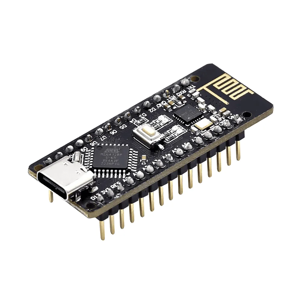
A standard NRF24L01+ setup usually means six jumper wires between the radio and the microcontroller, and those wires are a common source of intermittent faults. On the RF Nano V3.0 the radio is integrated, so the SPI bus is already routed and you mainly need to verify that your sketch uses the correct pins. The board is listed as Arduino Nano compatible with an ATmega328P and a compact 48x19mm footprint, which makes it a practical choice when you want a small transmitter or receiver without a second PCB.
The trade-off is that you cannot move the radio away from the microcontroller with a longer cable. If your project needs the antenna in a different position, a separate NRF24L01+ module on a breakout may still be the better fit.
Power and range expectations to set before you start
The catalog does not list an external antenna connector, PA/LNA amplifier, or a tested open-air range figure, so treat range as something you measure in your own environment rather than a guaranteed number. Indoor links are affected by walls, metal enclosures, and Wi-Fi congestion in the 2.4GHz band. Start with a short bench link, then increase distance in steps and note where packets start dropping.
Powering the board from a stable 5V source matters more than most people expect. USB power from a laptop is fine for bench tests, but for a permanent installation use a regulated supply and keep the board away from motors, relays, and switching regulators that can inject noise into the 2.4GHz path.
RF Nano V3.0 setup steps
- Confirm the board and pinout before wiring anything: Compare the physical board to a standard Arduino Nano pinout and identify the SPI pins used by the integrated NRF24L01+. The catalog lists the board as Nano compatible but does not publish a separate RF Nano pinout diagram, so verify against the board markings or seller documentation rather than assuming a custom layout. Common mistake: wiring external radio jumpers to a board that already has the radio integrated. If you cannot confirm the SPI pin mapping, stop and ask the seller before applying power.
- Power the board from a stable 5V source: Connect USB for initial programming, then move to a regulated 5V supply for standalone operation. Keep the board clear of motors and relays. Checkpoint: the board should enumerate and run a simple blink sketch before you add radio code. A board that resets when the radio transmits usually has a power or grounding problem, not a code problem.
- Install the RF24 library and run a minimal test sketch: Use the RF24 Arduino library and start with the basic transmit and receive examples. Set the same channel and address on both ends, and keep data rate low for the first test. Common mistake: changing multiple radio settings at once, which makes it impossible to tell which change fixed or broke the link. Change one radio parameter at a time and log the result.
- Validate a short-range link on the bench: Place transmitter and receiver a few metres apart with clear line of sight. Confirm that packets arrive consistently before moving to a longer distance. Checkpoint: if the link fails at close range, check the SPI pin definitions and the channel/address settings before suspecting the hardware. A link that works at one metre but not at ten is usually an antenna or environment issue, not a wiring issue.
- Increase distance in measured steps: Move the receiver away in fixed increments and record where packet loss begins. Keep notes on orientation, height, and nearby metal. Common mistake: testing range with the board inside a metal enclosure or flat against a wall, which can make a working link look broken. Record the distance and orientation at which the link first becomes unreliable; that is your practical range for this setup.
- Adjust channel and data rate only after the link is stable: If you see dropouts in a crowded 2.4GHz environment, try a different channel and a lower data rate. The catalog does not list a tested range or antenna gain, so treat any improvement as specific to your location and re-test after each change. Keep a simple test log so you can return to the last known-good settings.
Product facts
-
RF Nano V3.0 Arduino Compatible Board with NRF24L01+ Wireless Module: Arduino Nano compatible board with an integrated NRF24L01+ wireless module, ATmega328P microcontroller, and 2.4GHz wireless with BLE support. You can build a compact wireless node without wiring a separate radio, but you should plan for the fixed radio position and check that your sketch targets the Nano pinout.
RF Nano V3.0 Arduino Compatible Board with NRF24L01+ Wireless Module