Quick answer
Wire the ST7789V adapter over SPI: connect VCC to 3.3V, GND to ground, and the display and micro SD lines to your Arduino's SPI pins, then set the library for a 240x320 panel. Use 3.3V logic or level shifters, and keep the display and SD chip-select pins separate.
Why the logic level and pin mapping matter
The adapter accepts 3.3V and 5V logic, but the ST7789V controller itself runs at 3.3V. On a 5V Arduino Uno or Nano, the display usually works, but the micro SD card is less forgiving and can fail or corrupt data at 5V logic. If you plan to use the SD slot, power the module from 3.3V and use level shifters on the SPI lines, or choose a 3.3V board such as a 3.3V Pro Mini or ESP32.
Pin labels on these adapters vary. Some boards mark the display chip select as CS and the SD chip select as SD_CS; others use LCD_CS and SD_CS. Before wiring, identify which pin belongs to the display and which to the card, because swapping them will leave one device unresponsive.
Power and backlight trade-off
The module has a bright white LED backlight. On 3.3V boards, the backlight is typically tied to the 3.3V rail; on 5V boards, check whether the board includes a backlight resistor or driver. If the backlight pin is exposed, do not connect it directly to 5V without confirming the board's input rating. A dim or flickering backlight usually points to a weak 3.3V supply, not a library problem.
Step-by-step wiring and setup
- Identify the display and SD chip-select pins: Look for labels such as CS or LCD_CS for the display and SD_CS for the micro SD card. If the board is unlabeled, trace the pins with a multimeter or check the vendor's pinout before applying power. Label both chip-select wires before you connect anything else.
- Connect power and ground: Wire VCC to 3.3V and GND to ground. If you are using a 5V Arduino and the micro SD card, power the module from 3.3V and use level shifters on the SPI lines; otherwise the card may fail to initialize. Confirm the 3.3V rail can supply the display and card together, especially on small boards.
- Wire the SPI bus: Connect SCK to the Arduino SPI clock, MOSI to the SPI MOSI pin, and MISO to the SPI MISO pin if you are using the micro SD card. The display alone needs only SCK, MOSI, CS, and DC; MISO is required for the card. On a 5V board, place level shifters between the Arduino and the module's SPI lines when the SD card is in use.
- Connect the display control pins: Wire the display CS to a digital pin, DC (data/command) to another digital pin, and RST to a digital pin or to the Arduino reset line if the board has no reset pin. Tie the backlight pin to 3.3V or the board's backlight input as labeled. If the screen stays white, recheck DC and RST first; a missing DC connection is a common cause.
- Install and configure the TFT library: Use a library that supports the ST7789 controller, such as Adafruit ST7735 and ST7789 or TFT_eSPI. Set the panel size to 240x320 and match the rotation and color order to your module. In TFT_eSPI, edit the User_Setup file to select the ST7789 driver and define the pin numbers you wired. Compile and upload a simple fill-screen test before adding the SD card code.
- Test the micro SD card separately: Initialize the SD card with its own chip-select pin and run a card-info example. Keep the display CS pin high while accessing the card, and keep the SD CS pin high while drawing to the display. If the card fails, lower the SPI clock to 4 MHz or less and check that the card is formatted as FAT32. If the display works but the card does not, the SD chip-select pin or logic level is the usual culprit.
Product facts
-
LCD 2.4 inch 240×320 PCB Adapter Micro SD Card ST7789V: The ST7789V adapter measures 36 x 48 mm and supports both 3.3V and 5V logic. The compact size fits small enclosures, but the 5V logic support does not remove the need to check the micro SD card's voltage tolerance.
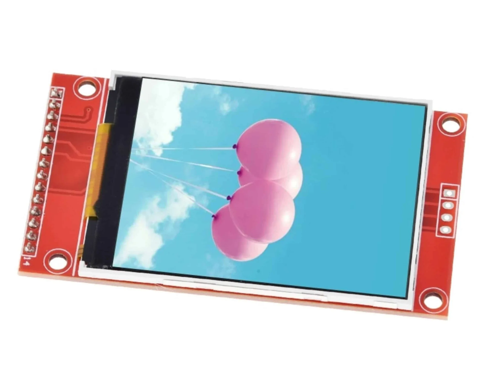
LCD 2.4 inch 240×320 PCB Adapter Micro SD Card ST7789V