Why Use a Logic Analyser with Arduino?
When your Arduino project behaves unexpectedly—a sensor reading jumps, a motor twitches, or communication drops—a logic analyser helps you see exactly what's happening on those signal lines. Unlike a multimeter that shows averages, a logic analyser captures the timing and shape of digital signals, making it an essential tool for debugging serial protocols, I2C buses, or custom logic circuits.
The Hobby Components USB 8CH 24MHz Logic Analyser brings this capability to hobbyist budgets. Paired with the free sigrok software suite, it offers features normally found on units costing much more. This guide walks through what you need to get started and how to connect it to your Arduino test setup.
What the Kit Includes
-
Hobby Components USB 8CH 24MHz Logic Analyser and Test Hook Clip Bundle: Our hugely popular low cost 8 channel analyser (HCTEST0006) is designed to work with the sigrok open-source signal analysis software suite giving this analyser a feature list normally found on analysers costing significantly more. The sigrok software is free and actively maintained, so you don't need expensive proprietary tools to decode your Arduino's digital signals.
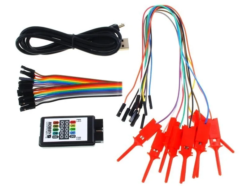
Hobby Components USB 8CH 24MHz Logic Analyser and Test Hook Clip Bundle
Connecting the Analyser to Your Arduino
The logic analyser captures eight channels simultaneously, which is ideal for monitoring multiple signals at once—for example, TX and RX lines on a serial link plus a few digital sensor outputs. To connect, you'll need test hook clips that attach to your Arduino's wires or pins.
The Test Hook Clips for Hobby Components Logic Analyser are purpose-built for this task. They come as a set of ten red clips attached to a ten-way female DuPont cable, about 28 cm long. This lets you clip onto individual wires without soldering or damaging insulation, and the DuPont connector plugs directly into the analyser's input.
Test Hook Clip Details
-
Test Hook Clips for Hobby Components Logic Analyser (Red): This set of ten red test hook clips is designed for use with the Hobby Components Logic Analyser. Each clip is attached to a ten-way female DuPont cable, providing a convenient and reliable connection for your testing needs. The clips make it easy to tap into your Arduino's signal lines temporarily, so you can debug without permanent wiring changes.
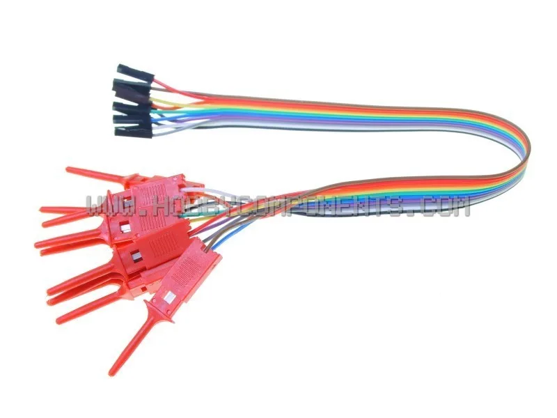
Test Hook Clips for Hobby Components Logic Analyser (Red)
Getting Started with sigrok and the Analyser
Follow these steps to begin capturing signals from your Arduino project. The exact commands depend on your operating system, but the general workflow is the same.
- Install sigrok: Download and install PulseView (the GUI front-end for sigrok) or the command-line sigrok-cli tools from the sigrok website. The software is open-source and available for Windows, macOS, and Linux.
- Connect the hardware: Plug the logic analyser into a USB port on your computer. Attach the test hook clips to the signals you want to monitor (for example, the TX and RX pins on an Arduino Uno).
- Configure PulseView: Open PulseView and select the Hobby Components 8CH 24MHz analyser as the device. Set the sampling rate and number of channels to match your test setup. Start the capture, and you'll see live waveforms of your Arduino's signals.
- Interpret the traces: Use the zoom and measurement tools in PulseView to examine pulse widths, timing between edges, and signal levels. This helps you spot glitches, timing errors, or protocol mismatches in your Arduino code.
Practical Tips for Digital Signal Analysis
When debugging an Arduino project, start with just one or two channels to keep the display readable. For serial communication, connect one clip to the TX pin and another to the RX pin. You'll see the actual bitstream as a waveform, which can reveal issues like incorrect baud rate settings, noise on the line, or missing start bits.
The 24 MHz sampling rate is more than enough for typical Arduino serial speeds (up to 115200 baud) and even faster protocols like I2C. If you're monitoring a slow sensor update, you can lower the sample rate to capture longer time windows.
Keep in mind that the test hook clips are designed for temporary testing. For permanent or high-vibration setups, consider soldering a dedicated breakout board. Also, the analyser does not generate its own test patterns—it only captures what's on the lines, so you'll need a known-good signal (like a simple 'Hello World' sketch) to verify your setup.