Quick answer
Use an XL6009 SEPIC module when your input voltage may be above or below the required output. Wire the input to your source, set the output with the trimpot while measuring with a multimeter, and connect the load only after the voltage is confirmed.
Why SEPIC handles both step-up and step-down
A SEPIC (single-ended primary-inductor converter) topology lets the XL6009 maintain a steady output even as the input crosses above or below the set voltage. Unlike a plain buck or boost converter, it does not need a manual mode switch when your source voltage drifts. This makes it useful for battery-powered projects where voltage sags over time, or for benchtop supplies that may be set higher or lower than the target.
When the XL6009 SEPIC is not the right choice
SEPIC converters are less efficient than dedicated buck or boost designs, so if your input is always well above or well below the output, a simpler topology will waste less power. Also, the XL6009 module does not include input reverse-polarity protection or output short-circuit protection by default—add a fuse or reverse-protection diode if those risks matter for your build.
Step-by-step setup for the XL6009 SEPIC module
- Connect input power: Solder or screw the input leads to the module’s IN+ and IN– terminals, observing polarity. Common mistake: reversing input polarity can destroy the module instantly—double-check before applying power. Use a labeled connector or color-coded wires to prevent accidental reversal.
- Set the output voltage without a load: Power the module and measure the output at OUT+ and OUT– with a multimeter. Turn the trimpot clockwise to increase voltage and counterclockwise to decrease until you reach your target. Common mistake: adjusting with a load connected can give a false reading—always set voltage unloaded first. Mark the final trimpot position with a dot of paint or nail polish to guard against drift.
- Verify regulation across input range: If your input will vary, test the output at the lowest and highest expected input voltages. The output should remain stable. Common mistake: assuming the module regulates perfectly at all extremes—check the datasheet or test with your actual source. If output drops at low input, your load may exceed the module’s capability at that voltage.
- Connect the load: With the output voltage confirmed, connect your device or circuit to OUT+ and OUT–. Common mistake: connecting a load that draws more current than the module can supply—check your load’s current draw against the module’s rated output. Add a fuse on the output if your load is expensive or sensitive.
- Power an Arduino or similar board: For Arduino projects, set the output to 5V or 7–12V depending on your board’s input requirements, then connect to the board’s VIN and GND. Common mistake: powering via USB and VIN simultaneously—disconnect USB when using the converter as the main supply. Use a multimeter to confirm 5V at the Arduino’s 5V pin if you bypass the onboard regulator.
Product facts
-
XL6009 DC-DC Stabilized Output Voltage Buck Boost Step UP/Down Converter(SEPIC): Output stays stabilized at the set voltage (e.g., 12V) regardless of whether input is 5V, 12V, or 32V. You can use the same module across different power sources without reconfiguring it for step-up or step-down operation.
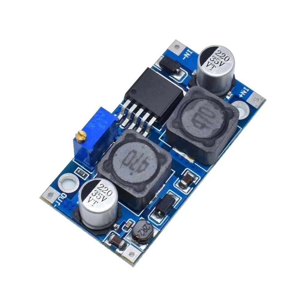
XL6009 DC-DC Stabilized Output Voltage Buck Boost Step UP/Down Converter(SEPIC)