Quick answer
For most antenna projects, choose a standard SMA female connector if your module has a male pin. Use an RP-SMA (reverse polarity) female connector when the module has a female socket. For PCB integration, an SMA PCB edge mount connector saves space and provides a reliable 50Ω interface up to 6 GHz.
SMA vs RP-SMA: The Polarity Difference
Standard SMA connectors use a female receptacle with a center hole and a male plug with a center pin. RP-SMA (reverse polarity) swaps the gender of the center contact: the RP-SMA female has a center pin, and the RP-SMA male has a center hole. This is a common point of confusion because the outer shell threading remains the same. Always check the center contact of your module or antenna before ordering.
PCB Edge Mount SMA Connectors
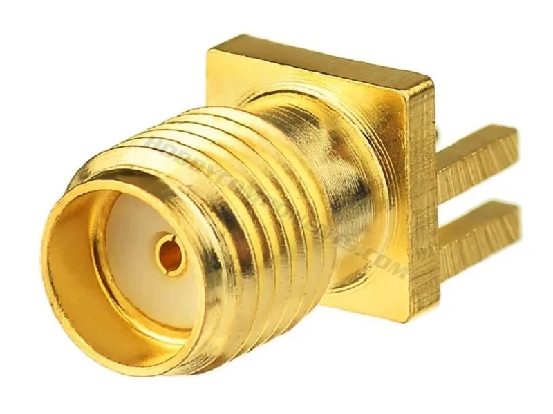
When you need to mount an SMA connector directly onto a PCB edge, a dedicated edge mount connector like the SMA Female PCB Edge Mount 4 Pin SMA Connector is the cleanest solution. It is designed for 1.6mm thick PCBs, offers 50Ω impedance, and handles frequencies up to 6 GHz. The gold plating ensures good conductivity and corrosion resistance. This type is ideal for custom antenna designs where you want to avoid pigtail cables and keep the signal path short.
Cable and Prototyping Considerations
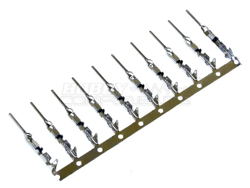
For breadboard prototypes or temporary antenna connections, you may need to build custom cable assemblies. The Male Pin Connector for Dupont Jumper Wire (2.54mm pitch) allows you to create a temporary link between an SMA breakout board and your microcontroller. While not a permanent RF solution, it is useful for initial testing and signal level checks before committing to a soldered connection.
Decision Rules for Choosing an SMA Connector
- Check the center contact first: Look at the center of your module’s SMA jack. If it has a hole, you need a standard SMA male (pin) connector. If it has a pin, you need an RP-SMA male (hole) connector. Mismatching polarity can damage equipment or cause no connection.
- Match impedance to your system: Most WiFi, Bluetooth, and LoRa antenna systems use 50Ω impedance. Ensure your SMA connector and cable are rated for 50Ω. The SMA Female PCB Edge Mount connector is specified for 50Ω. Using a 75Ω connector in a 50Ω system degrades signal and SWR.
- Consider frequency range: Standard SMA connectors are rated up to 18 GHz, but PCB edge mount variants may have lower limits. The edge mount connector listed here is rated to 6 GHz, which covers 2.4 GHz and 5 GHz WiFi, LoRa (868/915 MHz), and GPS. For sub-6 GHz projects, this connector is sufficient.
Product Facts
- SMA Female PCB Edge Mount 4 Pin SMA Connector: A gold plated PCB mounting female SMA connector designed to be edge mounted to a PCB of 1.6mm thickness. Impedance: 50 Ω, Frequency (max): 6 GHz, Voltage (max): 335 V, Isolation voltage: 1000 V rms, Durability: ≥ 500 cycles, Temp range: -65 to +165 °C. This connector provides a compact, direct solder-to-PCB solution for antenna projects, maintaining 50Ω impedance up to 6 GHz without extra cables.
- Male Pin Connector for Dupont Jumper Wire: Male pin connectors designed for use with Dupont jumper wires, featuring a standard 2.54mm pitch. Each pack contains 10 connectors, suitable for breadboard and prototyping projects. These pins let you quickly connect SMA breakout boards to breadboards for testing antenna circuits without soldering.
Which SMA Connector Fits Your Project?
Best for
- Custom PCB antenna designs needing a direct solder mount
- Projects requiring a compact 50Ω interface up to 6 GHz
- Builders who want to avoid pigtail cables and extra adapters
Not for
- Applications above 6 GHz (choose a higher-rated SMA or SMP connector)
- Situations where you need a panel-mount or bulkhead connector (choose a threaded bulkhead variant)