Quick Answer
An F10 aluminum BTA servo mount moves the servo behind the axle and above the link plane, so steering geometry and clearance change together. For F10 axles with a servo-on-top-of-axle mount, use the Incision VRD Tie Rod and Drag Link Set, which is built with bent rod ends on the tie rod for clearance and straight rod ends on the drag link. If you are not running that exact F10 axle and servo position, do not assume the same link set will clear.
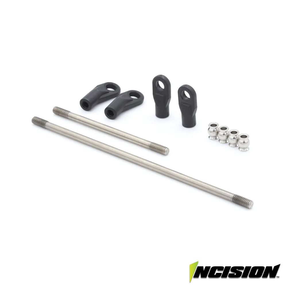
Incision VRD Tie Rod and Drag Link Set
Most F10 steering problems are not mystery problems. They come down to where the servo sits, how the tie rod and drag link route around the axle, and whether the links you bought were made for that layout. A behind-the-axle servo mount changes all three at once.
This FAQ answers the questions that come up most often when builders set up an F10 aluminum BTA servo mount: which links fit, what geometry actually changes, where clearance gets tight, and which Vanquish parts are worth checking while the front end is apart.
What does an F10 aluminum BTA servo mount actually change?
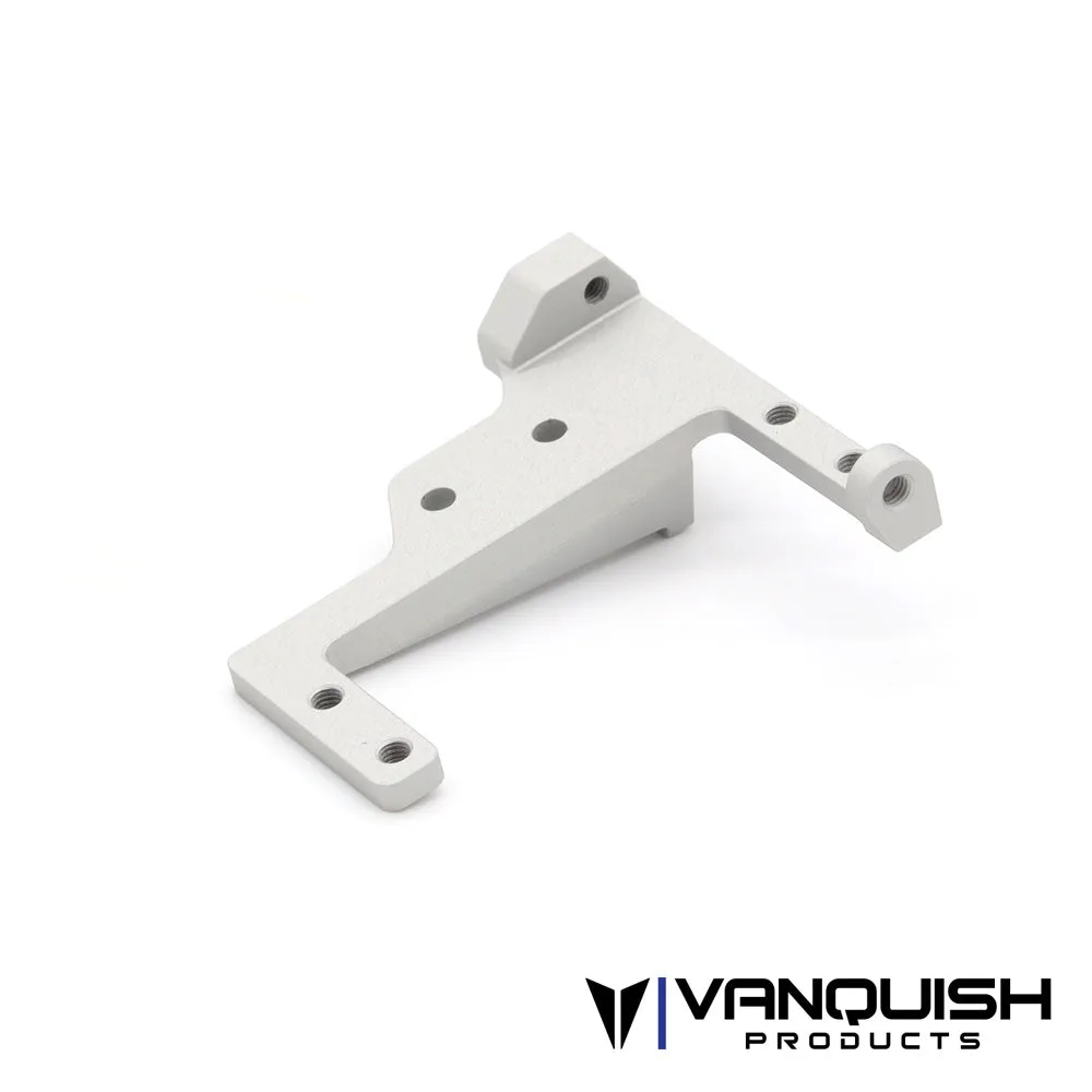
It relocates the steering servo behind the axle instead of leaving it on the axle or on the chassis rail. That single move changes the steering link angles, the load path into the axle, and the space available around the diff cover, links, and suspension travel. The aluminum construction matters less for geometry and more for holding the servo rigidly so the link angles you set do not drift under load.
The practical result is that you are not just bolting on a mount. You are committing to a steering layout. The tie rod and drag link lengths, the rod end style, and the servo horn position all have to match that layout. If any one of those is off, you get bump steer, binding, or a link that contacts the axle at full compression.
- Check servo position first, then order links, not the other way around.
- Set ride height and check clearance at full compression and full droop before final tightening.
Which link set fits an F10 BTA servo mount?
For F10 axles with a servo-on-top-of-axle mount, the Incision VRD Tie Rod and Drag Link Set is the matching link set. It includes a stainless steel tie rod, a stainless drag link, two Incision rod ends with pivot balls, and two Incision bent rod ends with pivot balls. The bent rod ends are used on the tie rod specifically for clearance, while the drag link uses straight rod ends.
That bent-versus-straight split is the detail that matters. If you substitute a generic link set with all straight ends, you may lose the clearance the bent ends were providing. If you are running a different axle or a different servo position, treat the Incision set as a starting reference rather than a guaranteed fit, because the catalog listing ties it to F10 axles and a servo-on-top-of-axle mount.
- Confirm your axle is an F10 and your servo is mounted on top of the axle before ordering.
- Keep the bent rod ends on the tie rod; swapping them to the drag link defeats the clearance design.
How does BTA steering geometry affect bump steer and drag link angle?
Behind-the-axle steering changes the relationship between the drag link and the suspension cycle. The goal is to keep the drag link roughly parallel to the link or axle path so the steering does not move as the suspension compresses and extends. When the drag link angle is wrong, the wheels steer themselves over bumps, which is bump steer.
You adjust this with servo horn height, horn offset, and link length, not by bending parts. Small changes at the horn make large changes at the wheel, so move in small increments and recheck. If you cannot get the drag link parallel without the link contacting something, the servo position or horn is the problem, not the link.
- Set the drag link parallel to the suspension link plane as a starting point.
- Recheck steering trim after any horn or link change; do not chase it with the transmitter.
Where does vanquish servo mount clearance usually get tight?
Clearance problems cluster in three places: the tie rod against the diff cover or axle housing at full compression, the drag link against the chassis or skid at full droop, and the servo body or horn against the upper links. The bent rod ends on the Incision tie rod exist to buy space in the first of those areas.
The only reliable way to find interference is to cycle the suspension by hand through its full travel with the wheels turned lock to lock. Do this before you finalize anything. If a link touches at one extreme, you have a geometry or mounting problem that will show up as a broken or bent part later.
- Cycle full compression, full droop, and full steering lock in both directions.
- Look for witness marks after the first run; they show where parts are actually contacting.
What else should I replace while the front end is apart?
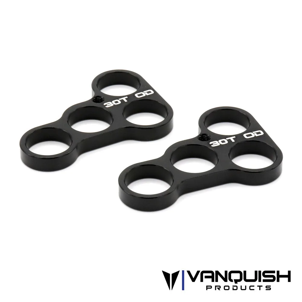
BTA steering puts more load through the servo and the front drivetrain, so it is a sensible time to inspect wear items. On the transmission side, the VFD Transmission 30t Bearing Plate Set is a replacement package for the VFD transmission, identified by SKU VPS10142 and listed under the VS4-10 platform parts. It includes two pieces of the 30t bearing plate replacement set.
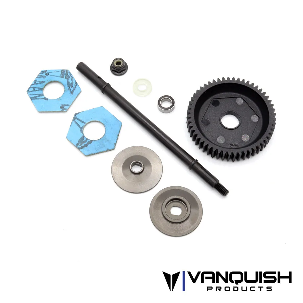
If you are running a VFD transmission with a slipper, the VFD Slipper Set is a direct replacement for the VFD Twin transmission or an option part for the standard VFD transmission found in the VS4-10 Pro, Ultra, or VPS10152. The installation note is specific: tighten the M4 locknut with a standard cross wrench, then back off half a turn, which should equal an estimated 60 oz/in torque spec. Do not guess at this setting.
- Inspect bearing plates for wear before ordering; the set includes two plates.
- Follow the slipper torque note exactly rather than tightening by feel.
Do I need a different servo or horn for BTA?
The mount does not dictate a specific servo, but it does change the load and the space. A servo with a tall body or a large horn can create clearance problems that did not exist in the stock position. If you already have a servo that fits and centers reliably, there is no automatic reason to replace it just because you moved to BTA.
The horn is the more common issue. Horn height and offset are your main tuning tools for drag link angle, so having a couple of options on hand is more useful than buying a new servo. Set the horn so the drag link runs cleanly through the travel, then confirm the servo does not stall or buzz at full lock.
- Reuse a known-good servo; spend the effort on horn selection and link angle instead.
- Listen for servo buzz at full lock, which signals binding or an endpoint set too far.
BTA Servo Mount Fitment Checklist
Axle and servo position
Confirm you have an F10 axle and a servo-on-top-of-axle mount before ordering links. If either is different, the Incision link set is a reference, not a guaranteed fit.
Rod end placement
Keep the bent rod ends on the tie rod and straight rod ends on the drag link. Swapping them removes the clearance the design provides.
Full travel check
Cycle full compression, full droop, and full steering lock in both directions before final tightening. Any contact at an extreme is a geometry or mounting problem, not a link problem.
Drag link angle
Aim for the drag link to run roughly parallel to the suspension link plane, adjusted with horn height and offset. If you cannot get it parallel, revisit servo position or horn, not link length.
Drivetrain wear items
Check bearing plates and slipper condition while the front end is apart. Replace worn parts now rather than after a failure on the trail.
Parts That Matter for This Setup
- Incision VRD Tie Rod and Drag Link Set: For F10 axles with a servo-on-top-of-axle mount, this set includes a stainless steel tie rod, a stainless drag link, two Incision rod ends with pivot balls, and two Incision bent rod ends with pivot balls. Bent rod ends are used on the tie rod for clearance, and straight rod ends are used on the drag link. This is the link set that matches an F10 BTA servo layout. The bent tie rod ends are the clearance feature, so keep them on the tie rod when assembling.
- VFD Transmission 30t Bearing Plate Set: Replacement part package for the VFD transmission, identified by SKU VPS10142 and listed under Vanquish VS4-10 platform parts. The package includes two pieces of the 30t bearing plate replacement set. If you are already in the front end and drivetrain, this is a direct replacement for worn bearing plates rather than a geometry change.
- VFD Slipper Set: A direct replacement for the VFD Twin transmission or an option part for the standard VFD transmission in the VS4-10 Pro, Ultra, or VPS10152. Tighten the M4 locknut with a standard cross wrench and back off half a turn, which should equal an estimated 60 oz/in torque spec. The torque note is the useful part here: it gives you a repeatable slipper setting instead of tightening by feel.
An F10 aluminum BTA servo mount is a geometry decision as much as a hardware purchase. Match the mount to the right axle and servo position, use the Incision VRD Tie Rod and Drag Link Set with the bent ends on the tie rod, and verify clearance through the full suspension travel before you call it done. If a link touches or the drag link will not sit parallel, fix the mounting and horn first, because no link set will correct a layout problem.